A villa is not a collage of pretty rooms—it is a single, coherent organism. The ground floor plan dictates the column grid for the roof. The section shows where the staircase from the first floor lands. The elevations reflect every shift in the plan.
Below is a fully coordinated set of plans for a 4-bedroom contemporary villa on a flat, 1,200 m² site. All dimensions are in millimeters (mm) and referenced to a common grid system (A–F along Y-axis, 1–5 along X-axis) with a finished floor level (FFL) of ±0.00 at ground floor.
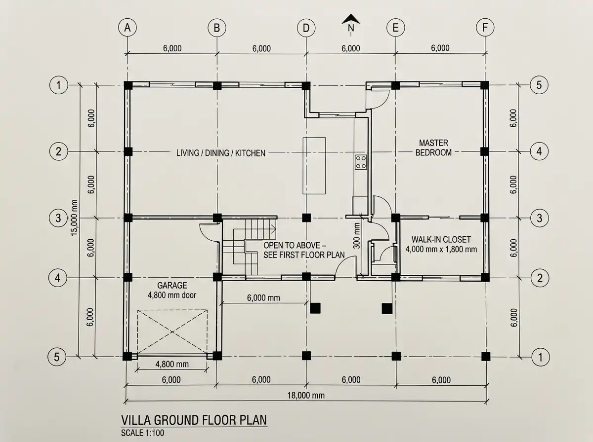
1. Ground Floor Plan (FFL ±0.00)
Key dimensions:
- Overall footprint: 18,000 mm (W) × 15,000 mm (D)
- Grid spacing: 6,000 mm in both directions (columns at A1, A3, C1, C3, etc.)
- Living room sliding glass wall: 6,000 mm wide × 3,000 mm high
- Kitchen island: 3,200 mm × 1,200 mm
- Stairwell opening: 2,500 mm × 4,500 mm (void above)
- Garage door: 4,800 mm wide × 2,400 mm high
Connection to other plans:
- The stair location (grid B2–C2) aligns exactly with the first floor bridge.
- The double-height void above the living room (grid A2–B3) is shown as a dashed zone.
- Column centers (A1, A3, C1, C3, etc.) are referenced on the roof plan.
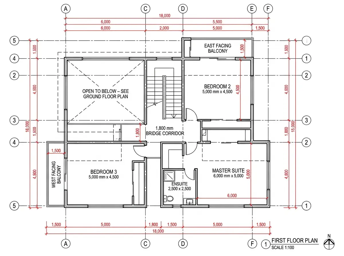
2. First Floor Plan (FFL +3,200 mm)
Key dimensions:
- Floor-to-floor height: 3,200 mm
- Bridge corridor width: 1,800 mm (clear)
- Bedroom 2 (East): 5,000 mm × 4,500 mm
- Bedroom 3 (West): 5,000 mm × 4,500 mm
- Master bedroom (South): 6,000 mm × 5,000 mm (with ensuite 2,500 mm × 2,500 mm)
- Void opening: 6,000 mm × 4,500 mm (centered over living room)
- Balcony depth: 1,500 mm (canted steel rail)
Connection to other plans:
- The void edge aligns exactly with the ground floor living room walls below.
- The stair landing at +1,600 mm aligns with the stair run shown in the section drawing.
- Column grid is identical to ground floor (columns continue through both floors).
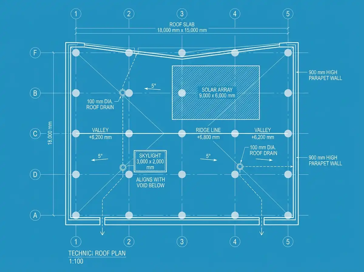
3. Roof Plan (FFL +6,800 mm)
Key dimensions:
- Roof slab thickness: 200 mm
- Parapet height: 900 mm (above roof slab)
- Butterfly roof slope: 5° (high point along grid line C, low points at grid lines B and D)
- Solar panel array: 9,000 mm × 6,000 mm (grid B3–D4)
- Skylight over void: 3,000 mm × 2,000 mm (centered on void below)
- Roof drain locations: Two at grid B2 and D4 (100 mm diameter)
Connection to other plans:
- Column grid matches exactly with ground and first floor.
- The butterfly roof high point runs along the same line as the first floor bridge (grid line C).
- Skylight is directly above the double-height void shown on ground and first floor plans.
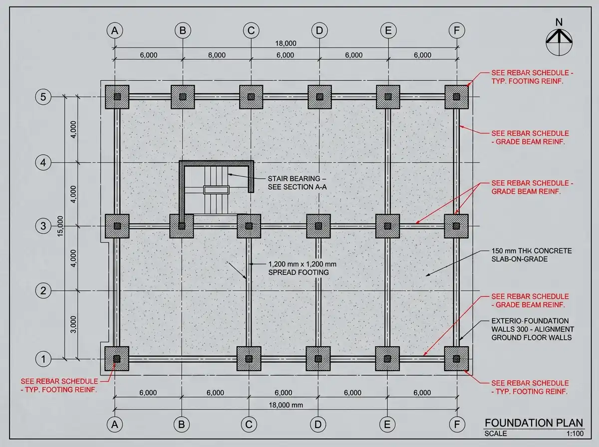
4. Foundation Plan (FFL –500 mm below grade)
Key dimensions:
- Spread footings: 1,200 mm × 1,200 mm × 400 mm thick at every column grid intersection
- Grade beam depth: 600 mm (connecting all footings)
- Slab-on-grade thickness: 150 mm (with 6 mm rebar at 300 mm centers)
- Foundation depth below grade: 500 mm to bottom of footing
Connection to other plans:
- Every column location (grid A1–F5) has a footing.
- The stair pit (where stair lands) is thickened to 300 mm slab.
- Foundation walls align with all exterior walls shown on ground floor plan.
5. All Four Elevations (North, South, East, West)
These elevations are derived directly from the plans. Every window, door, balcony, and parapet is located by its grid reference and vertical dimension.
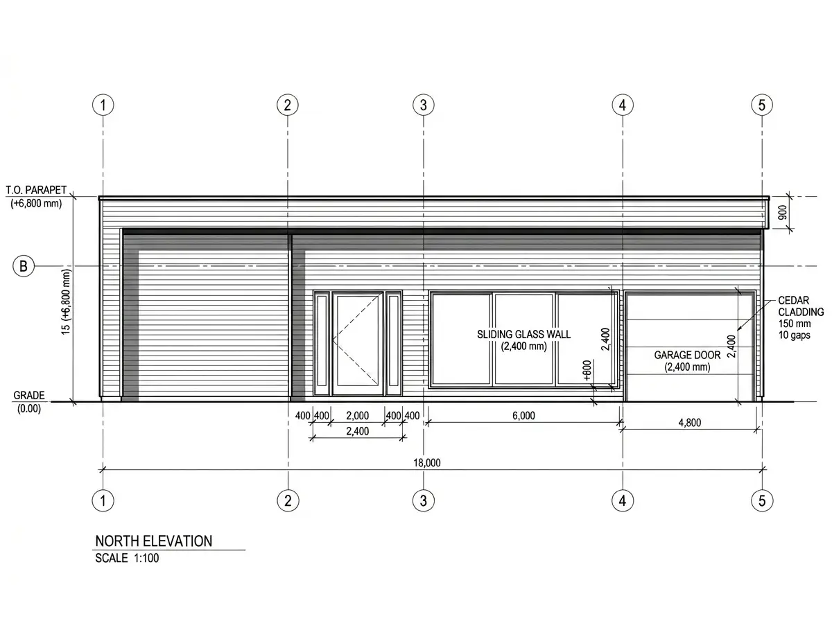
5.1 North Elevation (Facing Grid Line A, looking south)
Key dimensions & features:
- Overall width: 18,000 mm (grid 1 to 5)
- Overall height: 6,800 mm (ground to roof parapet)
- Garage door at grid A4–B5: 4,800 mm wide × 2,400 mm high (center at +1,200 mm above grade)
- Entry door at grid A2–A3: 2,000 mm wide × 2,400 mm high (with sidelites 400 mm each)
- Window – Living room: 6,000 mm wide × 2,400 mm high (sliding, at grid A2–B3, sill at +600 mm)
- Roof parapet: 900 mm high above roof slab, continuous
- Cladding: Horizontal cedar slats (150 mm face, 10 mm gap) except where glazed
Connection to plans:
- Garage door location matches ground floor garage.
- Living room window is exactly the 6,000 mm sliding door shown on ground floor plan.
- Parapet height matches roof plan.
5.2 South Elevation (Facing Grid Line F, looking north)
Key dimensions & features:
- Overall width: 18,000 mm
- Master bedroom (ground floor) window: 4,000 mm wide × 2,400 mm high (grid E3–F4)
- First floor master suite window: 4,000 mm wide × 1,800 mm high (directly above, sill at +3,800 mm)
- Terrace door (ground floor dining): 3,000 mm wide × 2,400 mm high (grid D2–E2)
- First floor balcony: 6,000 mm wide × 1,500 mm deep (cantilevered from grid D3–E4) with glass rail
- Wall finish: Polished stucco (light cream), with vertical stone accent at grid F3 (2,000 mm wide)
Connection to plans:
- Balcony location matches first floor plan (master suite balcony).
- Terrace door matches ground floor dining exit shown on plan.
- Window stacking (ground + first) aligns vertically.
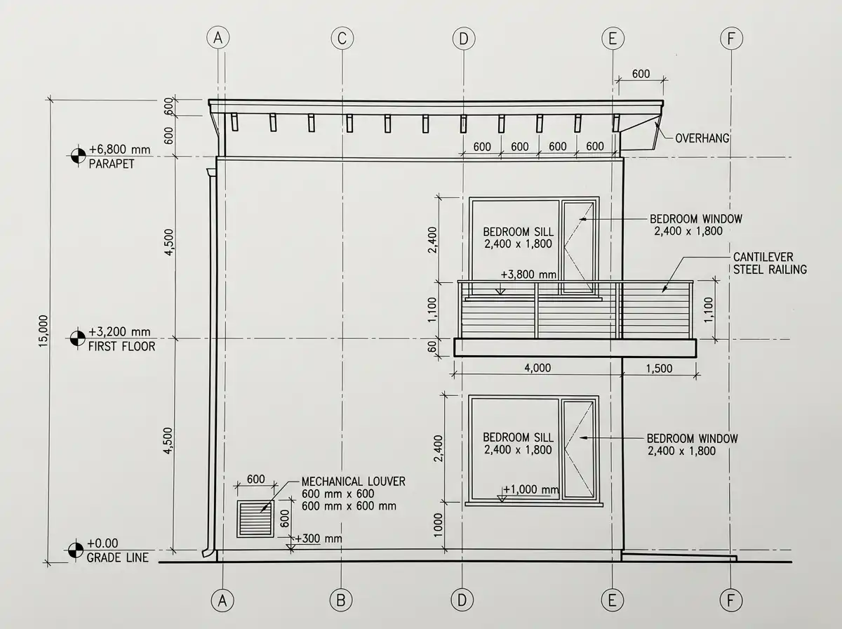
5.3 East Elevation (Facing Grid Line 5, looking west)
Key dimensions & features:
- Overall depth: 15,000 mm (grid A to F)
- Ground floor bedroom 2 window: 2,400 mm wide × 1,800 mm high (grid D5–E5, sill at +1,000 mm for privacy)
- First floor bedroom 2 window: 2,400 mm wide × 1,800 mm high (directly above, sill at +3,800 mm)
- Bedroom 2 balcony (first floor): 1,500 mm deep × 4,000 mm wide (cantilevered at grid D5–E5)
- Mechanical room louver: 600 mm wide × 600 mm high (grid A5, at +300 mm)
- Roof overhang: 600 mm beyond grid line 5, with exposed rafter tails
Connection to plans:
- Bedroom 2 is at grid D4–E5 on first floor plan.
- Balcony matches first floor plan (east-facing balcony called out earlier).
- Louver location aligns with mechanical room at grid A4–B5 on ground floor.
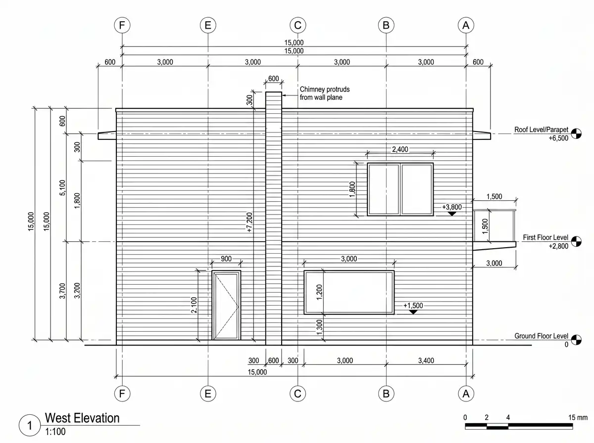
5.4 West Elevation (Facing Grid Line 1, looking east)
Key dimensions & features:
- Overall depth: 15,000 mm (grid A to F)
- Ground floor kitchen window: 3,000 mm wide × 1,200 mm high (grid B1–C1, sill at +1,500 mm, above counter)
- First floor bedroom 3 window: 2,400 mm wide × 1,800 mm high (grid A1–B1, sill at +3,800 mm)
- Bedroom 3 balcony (first floor): 1,500 mm deep × 3,000 mm wide (cantilevered at grid A1–B1)
- Chimney / exhaust flue: 600 mm wide × 2,400 mm high (grid C1–D1, protruding 300 mm from wall)
- Service door (ground floor pantry): 900 mm wide × 2,100 mm high (grid D1)
Connection to plans:
- Kitchen window aligns with kitchen counter run on ground floor plan (grid B1–C1).
- Bedroom 3 balcony matches first floor plan (west-facing balcony).
- Chimney location aligns with fireplace shown on ground floor plan at grid C2.
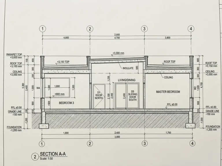
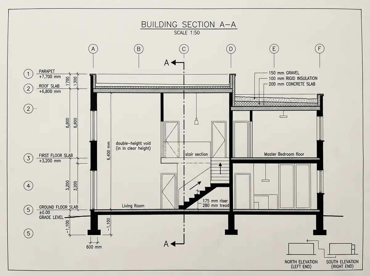
6. Building Section A-A (Cutting through Grid Line C, looking west)
Cut location: Along grid line C (east-west), from grid 1 to 5.
What it shows: The relationship between ground floor, first floor, roof, foundation, and the double-height void.
Key dimensions:
- Grade to ground floor slab: –500 mm (top of slab at ±0.00)
- Ground floor ceiling height: 3,200 mm (slab to slab)
- First floor ceiling height: 3,200 mm (slab to roof)
- Double-height void: 6,400 mm from ground floor slab to underside of roof
- Roof assembly: 200 mm slab + 100 mm rigid insulation + 150 mm gravel ballast
- Stair riser: 175 mm × tread: 280 mm (18 risers total)
- Foundation: 500 mm deep × 600 mm wide continuous wall under grid line C
Connection to plans:
- The cut passes through the stair (grid B2–C2), double-height void (grid A2–B3), and master bedroom (grid D4–F5).
- References the north and south elevations at each end of the cut.
Summary Checklist for Architectural Consistency
| Element | Connection Across Plans |
|---|---|
| Grid system | A–F, 1–5 at 6,000 mm centers – appears on every plan and section |
| Column locations | Same coordinates on foundation, ground, first floor, and roof |
| Stair | Same location (B2–C2) on ground, first floor, and section |
| Double-height void | Dashed on ground floor, open on first floor, skylight on roof |
| Balconies | Shown on first floor plan and corresponding elevations (East, South, West) |
| Window/door dimensions | Match between floor plans (location) and elevations (height/sill) |
| Roof parapet | Shown on roof plan (900 mm), all elevations, and section |