A 3BHK house is the most demanded typology worldwide. It must balance privacy (bedrooms), togetherness (living/dining), and service (kitchen, utility). Below is a fully dimensioned set for a 130 m² (1,400 sq ft) built-up area house on a 15 m × 20 m (300 m²) site.
Common reference system for all drawings:
- Grid lines: 1, 2, 3, 4 (along length) and A, B, C, D (along width)
- Grid spacing: 4,000 mm (center to center of columns/walls)
- Finished Floor Level (FFL): ±0.00 at ground floor
- All dimensions in millimeters (mm)
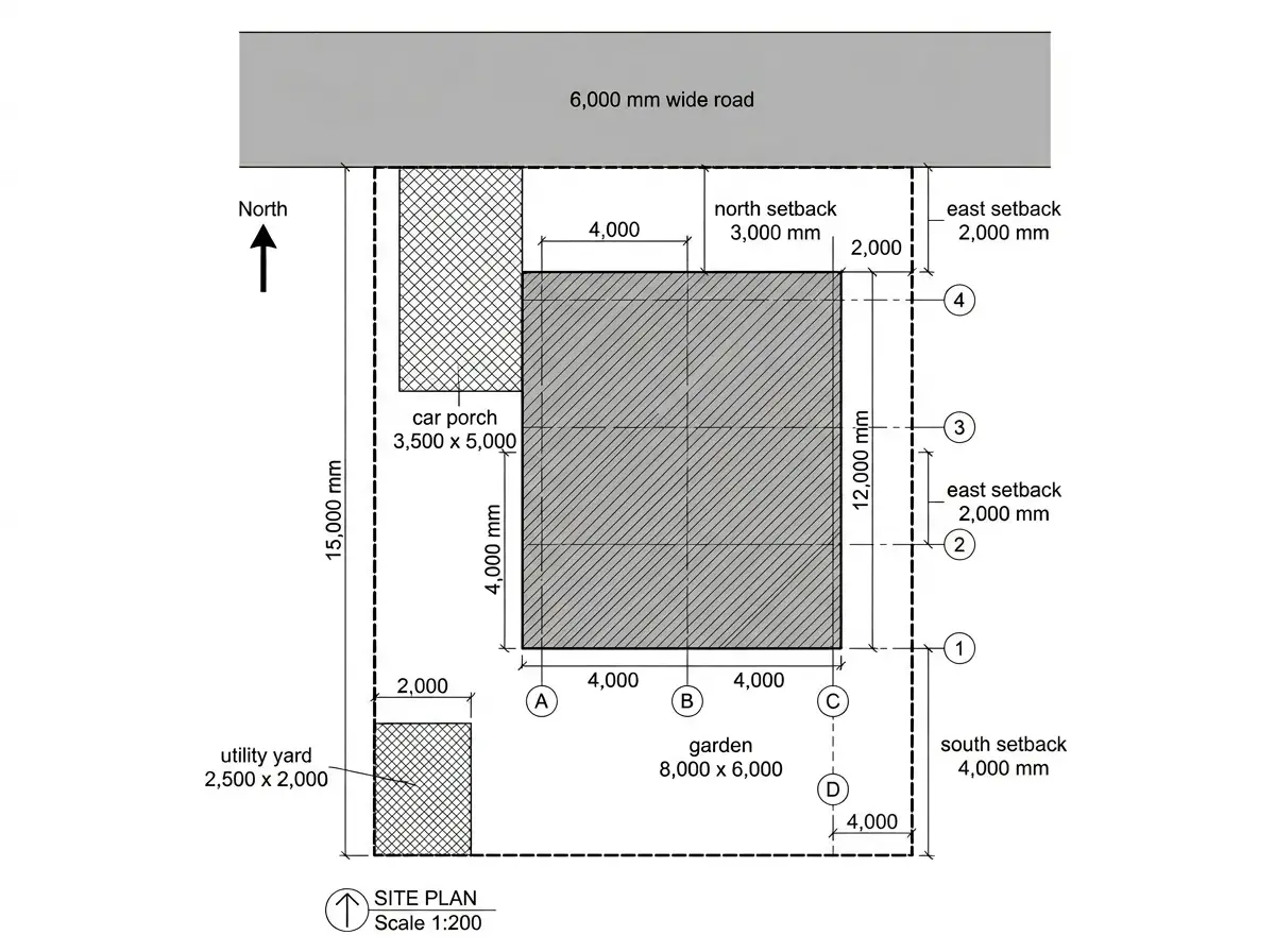
1. Site Plan (1:200 scale) – Context & Setbacks
Plot size: 15,000 mm (W) × 20,000 mm (D) = 300 m²
Building footprint: 11,000 mm × 12,000 mm = 132 m²
Setbacks:
- Front (North): 3,000 mm
- Rear (South): 4,000 mm (garden)
- Side (East): 2,000 mm
- Side (West): 2,000 mm (car porch)
Key features:
- Car porch: 3,500 mm × 5,000 mm (covered)
- Garden area: 8,000 mm × 6,000 mm (south)
- Utility/ service yard: 2,500 mm × 2,000 mm (west, behind kitchen)
- Rainwater harvesting pit: 1,500 mm diameter (north-east corner)
- Compost pit: 1,200 mm × 1,200 mm (south-west corner)
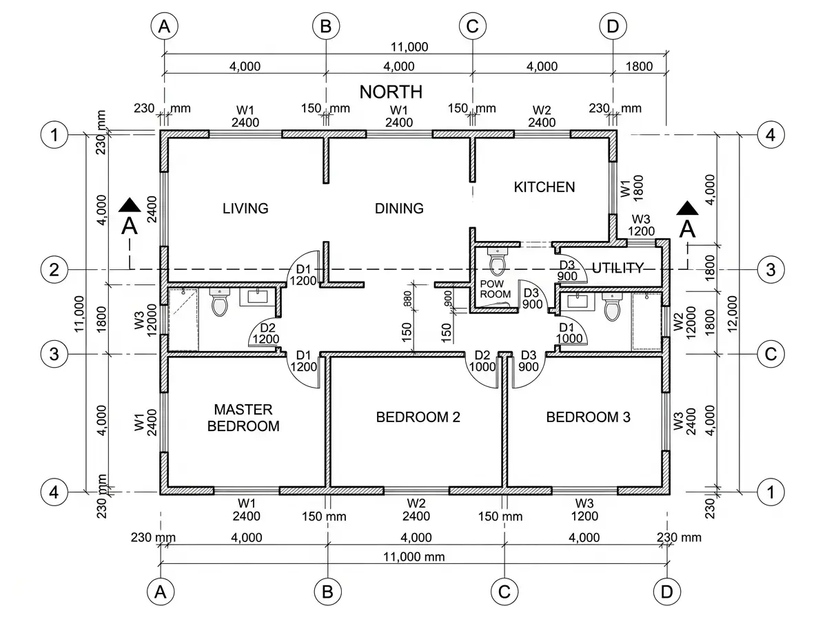
2. Ground Floor Plan (1:50 scale) – The Complete Layout
Overall building dimensions: 11,000 mm (grid 1 to 4) × 12,000 mm (grid A to D)
Wall thickness: 230 mm (external), 150 mm (internal)
Floor-to-ceiling height: 3,000 mm (clear)
Room Schedule with Dimensions:
| Room | Grid Location | Size (mm) | Area (approx.) |
|---|---|---|---|
| Living Room | A1–B2 | 4,000 × 4,000 | 16 m² |
| Dining Room | B1–C2 | 4,000 × 4,000 | 16 m² |
| Kitchen | C1–D2 | 4,000 × 3,500 | 14 m² |
| Master Bedroom (B1) | A3–B4 | 4,000 × 4,000 | 16 m² |
| Bedroom 2 (B2) | B3–C4 | 4,000 × 4,000 | 16 m² |
| Bedroom 3 (B3) | C3–D4 | 4,000 × 4,000 | 16 m² |
| Common Bathroom | D2–D3 | 2,500 × 2,000 | 5 m² |
| Master Bathroom | A4–B4 (en suite) | 2,500 × 2,000 | 5 m² |
| Powder Room (Guest WC) | A2–A3 | 1,500 × 1,500 | 2.25 m² |
| Utility/Store | D1–D2 | 2,000 × 2,000 | 4 m² |
| Corridor | B2–C3 | 1,500 × 8,000 | 12 m² |
Key Connections to Other Drawings:
- Window schedule (below) matches elevations
- Door types (D1, D2, D3) referenced in door schedule
- Column locations (at grid intersections) tie to foundation plan
- Section cut line A-A shown passing through living, corridor, and bedroom 2
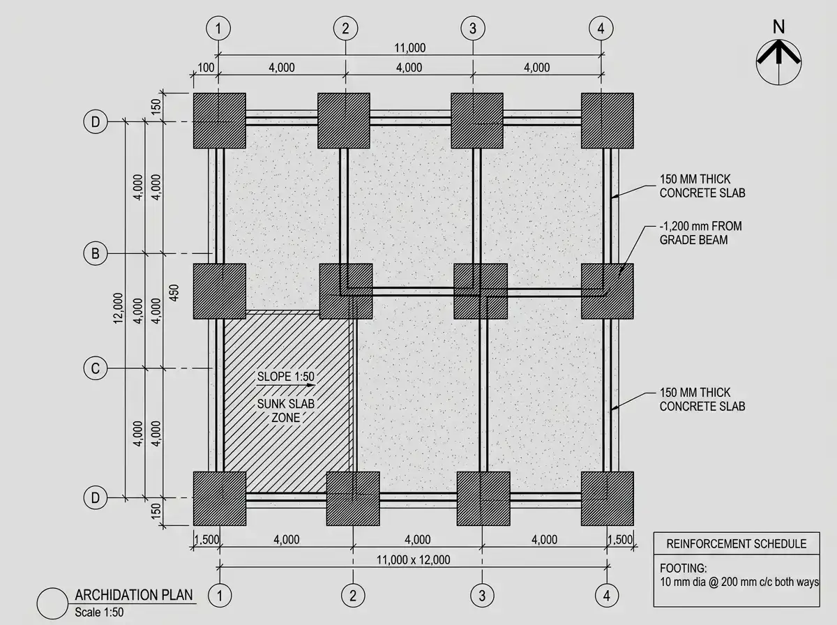
3. Foundation Plan (1:50 scale) – Structure Below
Derived from ground floor column grid: Same grid lines 1-4, A-D at 4,000 mm centers
Foundation elements:
- Isolated column footings: 1,500 mm × 1,500 mm × 400 mm thick at every grid intersection (16 total)
- Grade beams: 450 mm wide × 600 mm deep connecting all footings
- Floor slab: 150 mm thick reinforced concrete (M20 grade)
- Foundation depth: 1,200 mm below ground level (bottom of footing)
- Soil type assumed: Medium dense sand (bearing capacity 150 kN/m²)
Special zones:
- Under bathroom walls: 300 mm thick foundation wall (for plumbing)
- Under utility: Sunk slab 300 mm deep (for drainage slope)
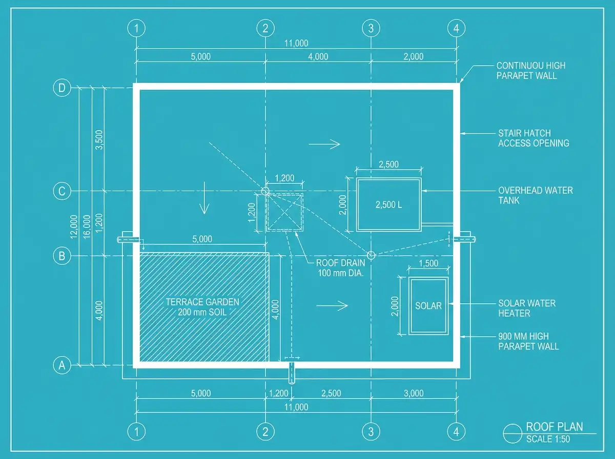
4. Roof Plan (1:50 scale) – The Fifth Facade
Roof type: Reinforced concrete flat slab with 1:40 slope to terrace garden
Dimensions:
- Roof slab thickness: 150 mm
- Parapet wall: 900 mm high (above roof slab)
- Roof area: 11,000 mm × 12,000 mm (same as building footprint)
Key elements:
- Terrrace garden (west side): 5,000 mm × 4,000 mm (grid A1–B2) with 200 mm soil depth
- Solar water heater: 2,000 mm × 1,500 mm (grid C4–D4)
- Roof drains: Two at grid B2 and C3 (100 mm diameter) with 150 mm downspouts
- Parapet drainage spouts: 300 mm wide openings at grid A2 and D3 (to throw water away from walls)
- Water tank (overhead): 2,500 mm × 2,000 mm × 1,500 mm high (grid B3–C4)
Connection to lower floors:
- Columns continue from ground floor (same grid)
- Staircase roof hatch: 1,200 mm × 1,200 mm at grid B2–C2 (directly above stair)
5. Door & Window Schedule
Door Schedule
| Mark | Type | Size (mm) | Location | Material | Swing |
|---|---|---|---|---|---|
| D1 | Main entrance | 1,200 × 2,100 | Living (grid A1–A2) | Teak wood frame, 45 mm solid core | Inward |
| D2 | Bedroom | 1,000 × 2,100 | All 3 bedrooms | Flush door, honeycomb core | Inward |
| D3 | Bathroom | 900 × 2,100 | All bathrooms | Waterproof PVC, louvered | Inward |
| D4 | Utility | 900 × 2,100 | Utility (grid D1) | Mild steel, powder coated | Outward |
| D5 | Sliding glass | 2,400 × 2,400 | Living to garden (grid A3–A4) | 12 mm tempered glass, aluminum track | Sliding |
Window Schedule
| Mark | Type | Size (mm) | Location | Sill height (from FFL) | Material |
|---|---|---|---|---|---|
| W1 | Sliding | 2,400 × 1,500 | Living (north) | 600 mm | Aluminum, 5 mm glass |
| W2 | Casement | 1,800 × 1,500 | Master bedroom (east) | 900 mm | UPVC, double glazed |
| W3 | Casement | 1,800 × 1,500 | Bedroom 2 (south) | 900 mm | UPVC, double glazed |
| W4 | Casement | 1,800 × 1,500 | Bedroom 3 (west) | 900 mm | UPVC, double glazed |
| W5 | Fixed | 1,200 × 600 | Bathrooms (high) | 2,100 mm | Frosted glass, aluminum |
| W6 | Sliding | 2,400 × 1,200 | Kitchen (west) | 1,100 mm (above counter) | Aluminum, 5 mm glass |
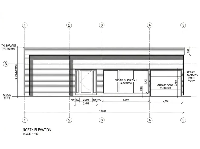
6. All Four Elevations (North, South, East, West)
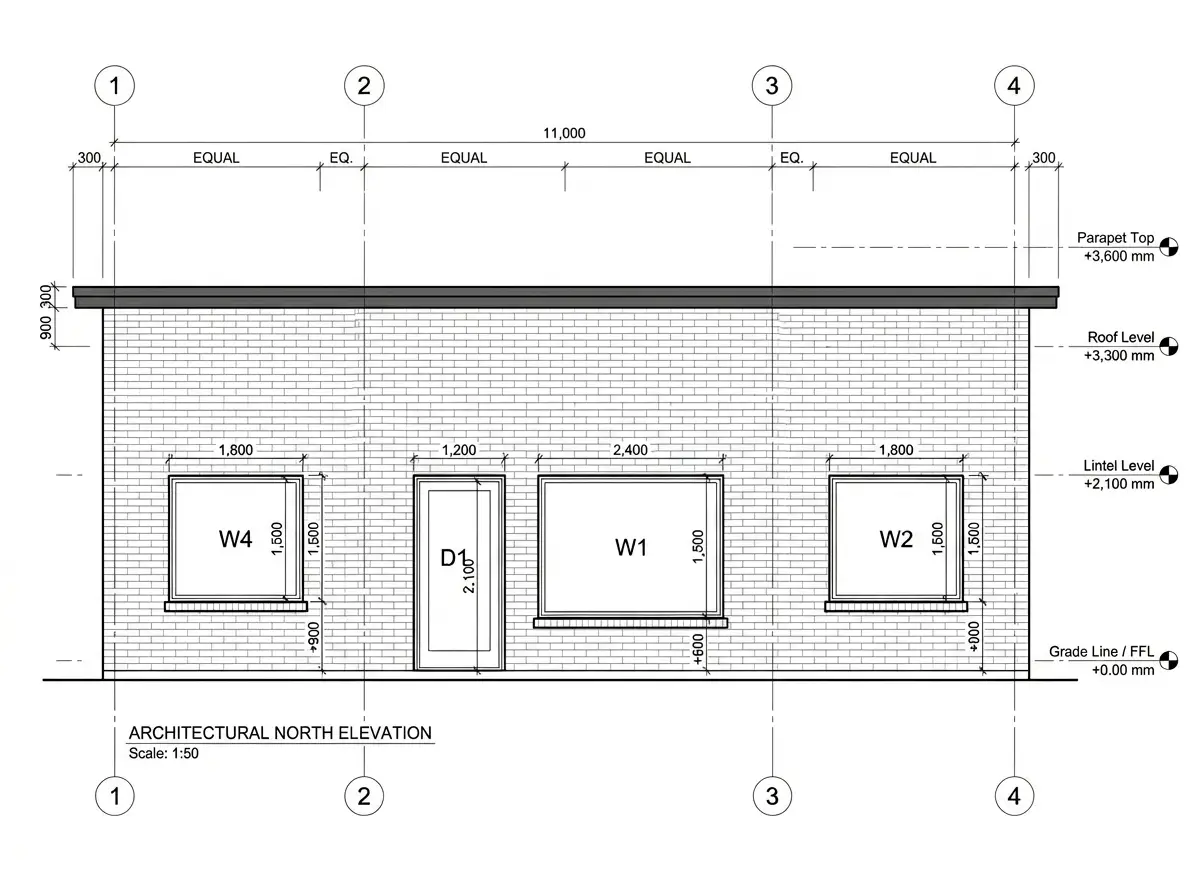
6.1 North Elevation (Front facade, facing road)
Width: 11,000 mm (grid 1 to 4)
Height: 3,600 mm (floor to top of parapet)
Elements from left to right (grid 1 to 4):
- Grid 1–2 (Bedroom 3 wall): W4 window (1,800 × 1,500 mm) at sill +900 mm
- Grid 2–3 (Living room): D1 main door (1,200 × 2,100 mm) + W1 window (2,400 × 1,500 mm)
- Grid 3–4 (Master bedroom): W2 window (1,800 × 1,500 mm) at sill +900 mm
- Roof parapet: 900 mm high with 300 mm overhang
- Wall finish: Exposed brick veneer (north facade only)
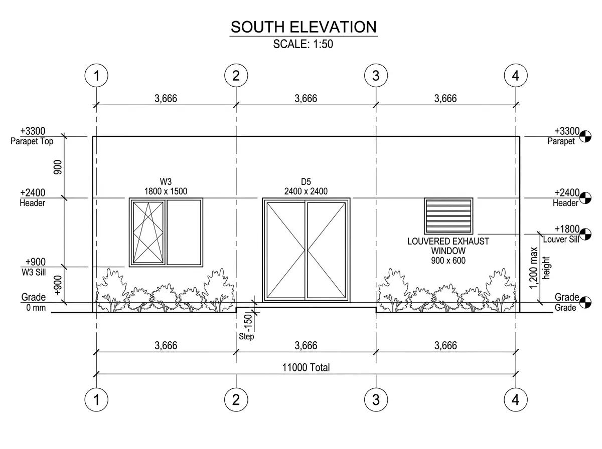
6.2 South Elevation (Rear facade, garden facing)
Width: 11,000 mm (grid 1 to 4)
Height: 3,600 mm
Elements:
- Grid 1–2 (Bedroom 2): W3 window (1,800 × 1,500 mm) at sill +900 mm
- Grid 2–3 (Dining room): D5 sliding glass door (2,400 × 2,400 mm) at grade (step down 150 mm to garden)
- Grid 3–4 (Utility wall): Small window (900 × 600 mm) for exhaust, louvered
- Wall finish: Smooth plaster with white cement paint
- Garden shown in elevation as low shrubs (1,200 mm high)
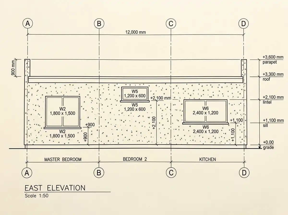
6.3 East Elevation (Side facade)
Width: 12,000 mm (grid A to D)
Height: 3,600 mm
Elements:
- Grid A–B (Master bedroom): W2 window (1,800 × 1,500 mm) at sill +900 mm
- Grid B–C (Bedroom 2): Small W5 bathroom window (1,200 × 600 mm) at sill +2,100 mm (high for privacy)
- Grid C–D (Kitchen): W6 window (2,400 × 1,200 mm) at sill +1,100 mm (above counter)
- No openings on this side except windows (neighbor setback 2,000 mm)
- Wall finish: Roughcast plaster (textured)
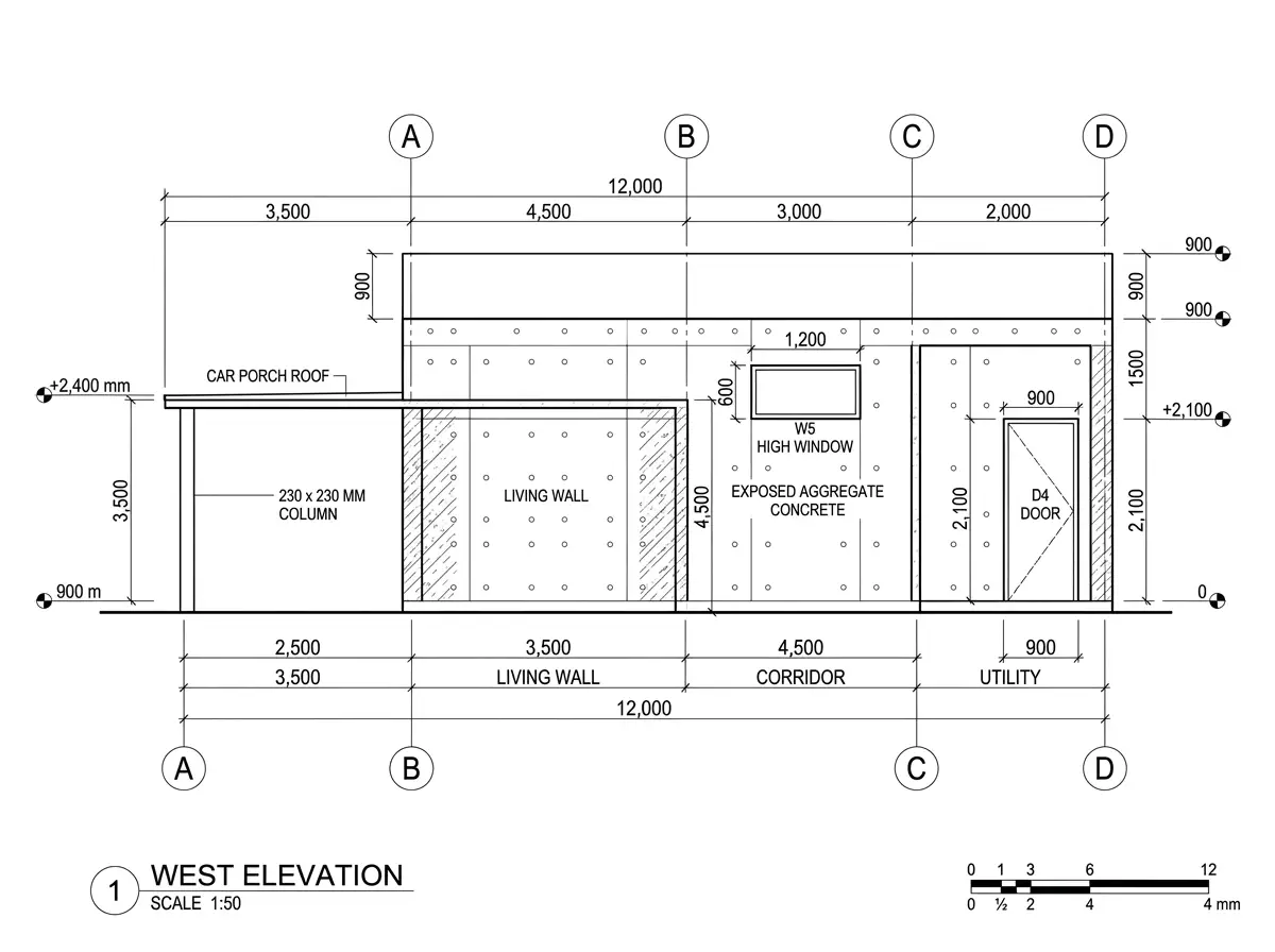
6.4 West Elevation (Side facade with car porch)
Width: 12,000 mm (grid A to D)
Height: 3,600 mm
Elements:
- Grid A–B (Living room side wall): No window (porch adjacent)
- Grid B–C (Corridor): W5 bathroom window (1,200 × 600 mm) at sill +2,100 mm
- Grid C–D (Utility): D4 utility door (900 × 2,100 mm) at grade
- Car porch roof (cantilevered) shown at +2,400 mm height, extending 3,500 mm from wall
- Car porch column: 230 mm × 230 mm at grid B (at 2,500 mm from building)
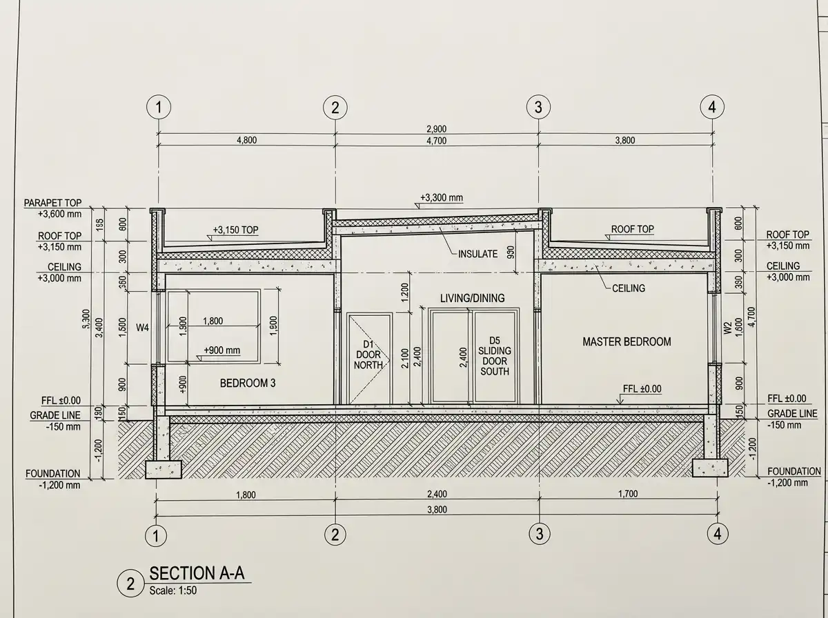
7. Section A-A (Longitudinal section through living, corridor, bedroom 2)
Cut location: Along grid line 2 (center of building), looking east
What it shows: Vertical relationship between all rooms, roof, foundation, and ground level
Key dimensions:
- Foundation bottom: –1,200 mm from grade
- Grade to FFL: –150 mm (slab top at ±0.00)
- Floor slab thickness: 150 mm
- Ceiling height (clear): 3,000 mm (FFL to underside of roof slab)
- Roof slab thickness: 150 mm
- Parapet height: 900 mm above roof slab
- Total building height (grade to parapet): 3,600 mm
Rooms visible in section (left to right = grid 1 to 4):
- Grid 1–2: Bedroom 3 (floor slab, W4 window, roof)
- Grid 2–3: Living/dining (D1 door at north, D5 door at south, higher ceiling if stepped – shown as 3,300 mm here)
- Grid 3–4: Master bedroom (similar to bedroom 3)
Construction layers annotated:
- Foundation: 1,200 mm deep, 600 mm wide
- Floor: 150 mm RCC slab + 50 mm screed + 10 mm tile finish
- Wall: 230 mm solid concrete block
- Roof: 150 mm RCC slab + 100 mm insulation + waterproofing + 50 mm screed
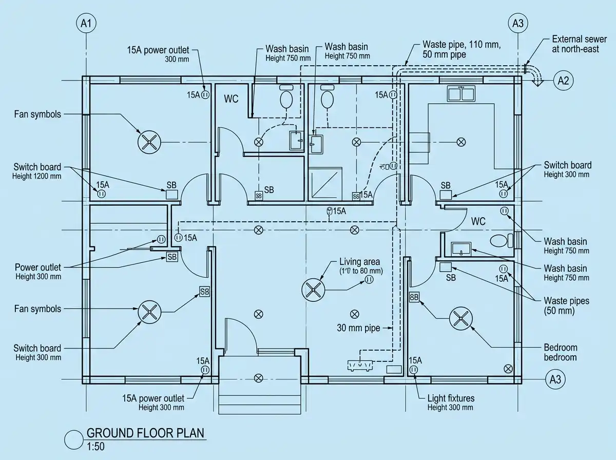
8. Electrical & Plumbing Schematic (Integrated Plan)
Electrical Layout (additive layer to ground floor plan)
| Fixture | Quantity | Location | Height (from FFL) |
|---|---|---|---|
| Ceiling fan | 5 | Each bedroom (1), living (1), dining (1) | – (on ceiling) |
| LED tube light | 12 | All rooms (2 per bedroom, 4 in living/dining) | – (recessed) |
| Switch board | 6 | Each room near door | 1,200 mm |
| Power outlet (15A) | 8 | Kitchen (3), utility (2), each bedroom (1) | 300 mm (counter: 1,100 mm) |
| TV point | 2 | Living, master bedroom | 600 mm |
| Exhaust fan | 3 | Each bathroom, kitchen | 2,100 mm |
Plumbing Layout
| Fixture | Quantity | Location | Waste pipe (mm) |
|---|---|---|---|
| WC (Indian/European) | 3 | Master bath, common bath, powder room | 110 mm |
| Wash basin | 3 | Same as above | 50 mm |
| Shower | 2 | Master bath, common bath | 50 mm |
| Kitchen sink | 1 | Kitchen | 75 mm |
| Utility sink | 1 | Utility | 50 mm |
| Floor drain | 2 | Utility, common bath | 75 mm |
Summary Coordination Matrix
| Element | Ground Floor | Foundation | Roof | Elevations | Section |
|---|---|---|---|---|---|
| Grid lines 1-4, A-D | ✓ | ✓ | ✓ | ✓ (as width ref) | ✓ |
| Wall locations | ✓ | ✓ (as grade beams) | ✓ (as parapet) | ✓ (as visible) | ✓ |
| Windows (W1-W6) | ✓ (location) | – | – | ✓ (size, sill height) | ✓ (if cut) |
| Doors (D1-D5) | ✓ (location, swing) | – | – | ✓ (size, height) | ✓ (if cut) |
| Columns | ✓ (at grids) | ✓ (footings) | ✓ (parapet at grids) | – | – |
| Floor level | ±0.00 | – | +3,300 | +0.00 | ±0.00 |
| Roof level | – | – | +3,300 slab | +3,300 | +3,300 |
Final Notes for Construction
- All dimensions are in millimeters – do not scale from drawings
- Grid lines are physically marked on site before construction
- Start with foundation plan – footings must be exactly at grid intersections
- Build walls to match door/window schedules – rough openings: add 50 mm on each side
- Cross-check elevations before ordering windows – sill heights are critical for furniture placement
With this set, any competent contractor can build this 3BHK house without ambiguity. Each drawing asks: “Where is this on the grid?” and answers it.